Turbidity sensor assembly: Building a first prototype (Part 2 – CAD, 3D printing)
In a previous blog post, I had written about the electronics of the sensor and how to put together the prototyping breadboard. Here I will outline how to properly do this turbidity sensor assembly. How to actually assemble this first, “fully-functional” (i.e. waterproof, in-situ) prototype of the turbidity sensor including its sensing head and the waterproof housing.
Sensing head
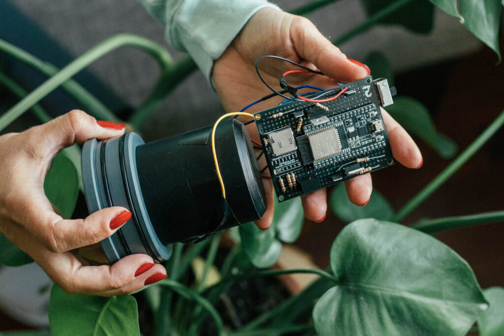
The first and hardest part of the entire sensor construction is making the sensing head (you can see it to the left of the image below in black PVC). We made two versions of this sensing head, one with machined PVC and the other with 3D-printed PLA. Both sensor heads used black material in order to minimize internal reflections inside of the head. I will outline both versions here.
Machined PVC
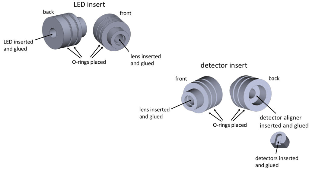
The image above shows the machined PVC version of the sensor. Our in-house technician made this one. They ordered a solid piece of black PVC and out of this piece, machined 6 components:
- the head (CAD file called Rohr.SLDPRT)
- the LED insert (LED_Zapfen.SLDPRT)
- the detector inserts x2 (Detector_Zapfen.SLDPRT) and aligners x2 (Detector_rückenteil.SLDPRT)
You can find all of the CAD files for these pieces in the following Github repository. Below I’ve made an image that shows how to assemble the components listed above. We first glued the detectors into the aligners, which we then subsequently glued into the detector inserts. The LED is glued into the LED insert. O-rings are placed on both the LED and detector inserts and these inserts are then placed into the sensing head.
3D printed sensing head
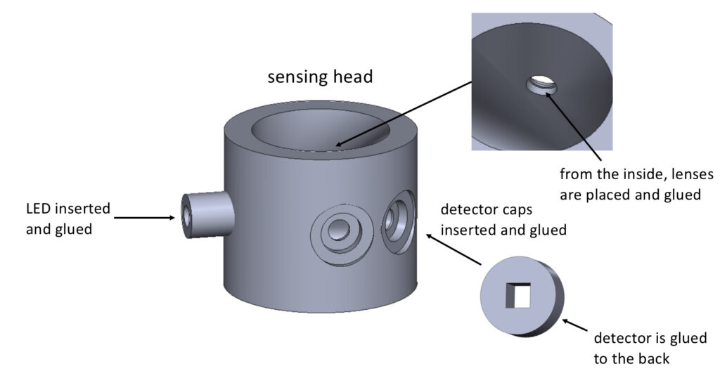
An alternative to the machined PVC is to 3D print the sensing head. You can do this by either converting the machined PVC CAD files to .STL files and repeating the steps above (but I haven’t tried this method so I don’t know if the parts are too small to 3D print nicely), or you can use the CAD/STL files provided in this repo. There are several different versions of the sensing head in this repo with numbers in their names like “180,” “135,” and “135_45” and these elude to the different detector locations (detector angles relative to the LED). I’m not going to go into the effect of these different angles in this post (I will do so in a future post). What is important now is that to build this sensing head you need to print 3 pieces:
- the head (e.g. Tubing135_45_V3.SLDPRT)
- the detector caps x2 (detectorcapsV3.SLDPRT)
The image below shows the assembled sensor. Be sure to smooth the 3D printed PLA with sandpaper before construction so that everything can be glued and placed as precisely as possible.
Waterproof housing

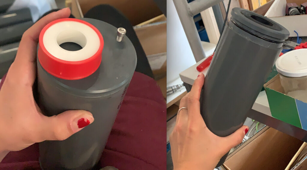
The waterproof housing is probably the easiest part of the sensor to make. It’s by no means perfect or the best way to make a waterproof casing, it’s just the quickest and best solution I was able to come up with. We made the housing from simple PVC from the hardware store. The technician machined a “cap” and glued it to the PVC tube to close one end of the sensor. They also made an adapter to fit/seal the sending head to the housing. All three components are shown in the image to the right and can be found at this github repo with the following names:
- cap is Deckel.SLDPRT
- pvc tubing is Aussenhülle.SLDPRT
- adapter is zapfen.SLDPRT
The adapter is glued to the sensing head (its CAD design needs to be adjusted (inner diameter) when using the 3D printed sensing head) and when combined with o-rings and vacuum grease, a watertight seal is created. Actually, an airtight seal is created! Which I only found out moments before starting my mixing tank experiments. So I actually couldn’t close my sensors because I was trying to compress the air inside of the sensor when attempting to close it. My last-minute quick fix to this issue was drilling a threaded hole in the housing, closing the housing, then closing the hole with a screw and nylon tape.
There are a lot of things missing in this design like a wiper and somewhere for the bubble to escape, but that will come in version 2.0 😉